Industry News
Curation by industry experts
Hot Articles
Popular Tags
What affects heat exchanger thermal efficiency most?
For technical evaluators, heat exchanger thermal efficiency is not determined by a single specification but by the interaction of flow design, temperature approach, surface condition, material conductivity, fouling resistance, and operating stability. In critical HVAC, cold-chain, and industrial thermal systems, even small deviations in these factors can increase energy consumption, reduce capacity, and compromise lifecycle performance. This article examines the variables that most strongly influence efficiency, helping procurement and engineering teams benchmark equipment with greater accuracy and make decisions aligned with long-term operational resilience.
In large-scale thermal infrastructure, a heat exchanger is rarely evaluated in isolation. It operates inside chillers, heat recovery systems, process skids, data-center cooling loops, pharmaceutical storage networks, and food cold-chain facilities where uptime, temperature stability, and energy intensity are linked.
For G-TSI’s technical evaluation context, the central question is not only whether a unit reaches its rated duty on a factory test bench. The more important issue is whether heat exchanger thermal efficiency remains stable across 3,000–8,000 annual operating hours under real fouling, load variation, and maintenance constraints.
The Core Variables Behind Heat Exchanger Thermal Efficiency
Heat exchanger thermal efficiency depends on how effectively heat moves from one fluid stream to another while minimizing avoidable losses. In engineering terms, evaluators typically examine heat duty, overall heat transfer coefficient, temperature approach, pressure drop, and effectiveness.
A common procurement mistake is comparing units by nominal capacity alone, such as 500 kW or 2 MW. Capacity is useful, but it does not reveal how the unit performs at partial load, after 12 months of service, or under non-ideal flow conditions.
Temperature Difference and Approach Temperature
The driving force for heat transfer is the temperature difference between the hot and cold fluids. A larger log mean temperature difference can increase transfer rate, but system design often demands close temperature approach values.
In HVAC and cold-chain applications, approach temperatures of 2°C–5°C may indicate high effectiveness, but they often require more surface area, tighter control, and careful fouling management. A smaller approach is not automatically better if pumping energy rises sharply.
Overall Heat Transfer Coefficient
The overall heat transfer coefficient, usually expressed in W/m²·K, combines convection on both fluid sides, conduction through the wall, and resistance from deposits. Even a thin fouling layer can reduce practical performance more than a material upgrade improves it.
For plate heat exchangers, high turbulence can improve transfer coefficients. For shell-and-tube equipment, baffle design, tube layout, and pass configuration play a major role. Each design balances efficiency, cleanability, pressure loss, and operating risk.
Key Technical Inputs to Check
- Design heat duty at minimum, nominal, and peak load conditions.
- Hot-side and cold-side inlet and outlet temperatures with allowable tolerance, often ±0.5°C–1.0°C.
- Pressure drop limits for each circuit, typically defined in kPa or bar.
- Fluid properties, including viscosity, density, specific heat, and contamination risk.
- Expected cleaning interval, such as quarterly, semi-annual, or annual maintenance.
The following table summarizes the main variables that technical evaluators should prioritize when benchmarking heat exchanger thermal efficiency across HVAC, industrial, and cold-chain infrastructure.
The table shows why heat exchanger thermal efficiency is a system-level result. A design with a tight approach temperature can still underperform if pressure drop forces pumps to run harder or if the fouling allowance is unrealistic.
Flow Design, Surface Geometry, and Pressure Drop Trade-Offs
Flow arrangement is one of the strongest determinants of heat exchanger thermal efficiency. Counterflow designs usually provide better thermal performance than parallel flow because they maintain a more favorable temperature gradient across the heat transfer length.
In practical infrastructure projects, however, geometry is constrained by floor space, maintenance clearance, vibration limits, and pipe routing. A unit with excellent theoretical effectiveness may be rejected if cleaning requires excessive downtime or if installation space is limited to 2–4 meters.
Plate, Shell-and-Tube, and Finned Designs
Plate heat exchangers offer compact surface area and high turbulence, making them common in district cooling, chiller plant optimization, and heat recovery loops. Their efficiency can be high, but gasket selection and channel fouling must be considered.
Shell-and-tube exchangers are widely used in industrial thermal management because they tolerate larger temperature ranges, higher pressures, and more challenging fluids. They may be less compact, yet they often provide stronger maintainability for severe service.
Finned-tube designs are relevant when one side is air. In air handling units, dry coolers, and refrigeration condensers, fin spacing, air velocity, and coil cleanliness can change efficiency within weeks during dusty or humid operation.
How Flow Choices Affect Evaluations
- Confirm whether the design is counterflow, crossflow, multi-pass, or mixed arrangement.
- Compare thermal duty with pump or fan power at the same operating point.
- Check whether the unit maintains performance at 30%, 60%, and 100% load.
- Review access panels, removable bundles, or clean-in-place compatibility.
A balanced evaluation should avoid the false choice between maximum turbulence and minimum pressure drop. The preferred solution is the one that meets heat duty while keeping total energy consumption and service complexity within project limits.
Fouling, Scaling, Corrosion, and Surface Condition
Among long-term operating variables, fouling often has the most visible impact on heat exchanger thermal efficiency. Deposits increase thermal resistance, reduce flow area, elevate pressure drop, and push compressors, pumps, or boilers away from efficient operating zones.
In cooling-water systems, common risks include mineral scaling, biofilm, suspended solids, and corrosion products. In food and pharmaceutical cold-chain systems, hygiene requirements add another layer because cleaning protocols must protect both efficiency and product integrity.
Why Fouling Allowance Matters
A fouling factor is not a decorative line in the datasheet. It is a design assumption about how much resistance the equipment can tolerate before performance becomes unacceptable. If the allowance is too optimistic, derating may appear within 3–6 months.
Technical evaluators should compare supplier proposals under the same fouling assumptions. Otherwise, a lower-cost selection may look efficient only because it assumes cleaner water, lower viscosity, or less contamination than the site can realistically provide.
Practical Fouling Control Measures
- Use filtration sized to expected particle load, not only nominal flow rate.
- Monitor inlet and outlet temperatures weekly during commissioning and monthly during stable operation.
- Track pressure drop trends; a 15%–25% increase may indicate developing blockage.
- Select materials compatible with chloride levels, pH range, and cleaning chemicals.
- Plan cleaning intervals before procurement, not after efficiency has declined.
The most reliable approach is to treat fouling management as part of the specification. A heat exchanger purchased without water quality, filtration, and service planning may lose more value than it saves in initial capital cost.
Material Selection and Operating Stability in Critical Infrastructure
Material selection influences both thermal performance and asset durability. Copper alloys may provide strong conductivity in suitable water conditions, while stainless steel, titanium, or higher-grade alloys may be preferred for corrosive or hygienic environments.
For evaluators working with hospitals, pharmaceutical warehouses, airports, district energy networks, or industrial parks, heat exchanger thermal efficiency must be assessed alongside availability targets. A 1%–3% efficiency gain is less valuable if corrosion risk increases downtime.
Stability Across Load and Climate Conditions
Extreme climate events have made design margins more important. A chiller plant or cold storage hub may need to operate through heat waves, peak electricity tariffs, and rapid load swings within the same 24-hour period.
Heat exchangers should therefore be reviewed at multiple operating points, not only design-day conditions. Evaluations often include minimum load, average seasonal load, peak load, and upset scenarios such as partial flow or elevated entering-water temperature.
The following table presents a practical benchmark framework for matching exchanger type, material direction, and evaluation priority in several infrastructure environments relevant to G-TSI’s industrial pillars.
The key conclusion is that material selection should not be separated from operating context. A material with lower conductivity may still deliver better lifecycle efficiency if it resists fouling, corrosion, and cleaning damage over 5–10 years.
How Technical Evaluators Should Benchmark Supplier Proposals
Supplier datasheets can present heat exchanger thermal efficiency in different ways, which makes direct comparison difficult. One proposal may emphasize effectiveness, another may highlight heat duty, while a third may present only outlet temperature and pressure drop.
To normalize proposals, evaluators should request a consistent calculation basis. This includes fluid properties, inlet temperatures, flow rates, fouling factors, allowable pressure drops, ambient assumptions, and expected operating hours per year.
A 5-Step Evaluation Method
- Define duty cases: minimum, average, peak, and emergency operating points.
- Standardize inputs: use the same temperatures, flow rates, fluid data, and fouling factors for all bids.
- Compare energy impact: calculate pump, fan, compressor, or boiler consequences, not only exchanger performance.
- Review maintainability: check access, cleaning tools, spare parts, gasket replacement, and shutdown time.
- Validate compliance: align design documentation with relevant ASHRAE, ISO, EN, or project-specific standards.
Questions to Ask Before Approval
Before approving a purchase, engineering and procurement teams should challenge assumptions. If a supplier cannot explain the calculation basis, uncertainty remains around real heat exchanger thermal efficiency after installation.
- What performance tolerance applies to the quoted duty, such as ±5% or another stated range?
- Is the quoted pressure drop clean, fouled, or end-of-cycle?
- How does efficiency change when flow falls to 50% of design?
- What cleaning method is recommended, and how many hours of downtime are expected?
- Are inspection reports, hydrostatic tests, or performance calculations included in delivery documentation?
A robust benchmarking process reduces the risk of selecting equipment that performs well only on paper. It also gives procurement directors a transparent basis for total cost comparison, warranty review, and lifecycle planning.
Common Misinterpretations That Distort Efficiency Decisions
Several recurring misunderstandings can distort heat exchanger selection. The first is assuming the highest thermal effectiveness is always the best option. In reality, greater surface area, tighter channels, or higher turbulence may increase cost and maintenance exposure.
The second misunderstanding is ignoring part-load behavior. Many systems operate below full load for more than 50% of annual hours. If the exchanger is poorly matched to those conditions, annual energy performance may disappoint.
Efficiency Is Not Only a Factory Rating
Factory testing is valuable, but site conditions are different. Water quality, air contamination, control sequencing, insulation, valve authority, and sensor calibration all influence whether the installed unit reaches expected heat exchanger thermal efficiency.
A third mistake is separating controls from hardware. In modern HVAC and cold-chain systems, variable-speed pumps, smart valves, and building automation algorithms can either support efficient heat transfer or create unstable flow conditions.
Risk Indicators During Operation
- Outlet temperature drift beyond 1°C–2°C under stable load.
- Pressure drop increasing for 2–3 consecutive monitoring periods.
- Pump speed rising while delivered heat duty remains unchanged.
- Unexpected compressor lift or boiler firing rate after seasonal changes.
- Frequent manual control overrides by facility operators.
These indicators should trigger investigation before performance loss becomes expensive. Early corrective action may involve flushing, chemical treatment, sensor recalibration, valve adjustment, or revised control sequences.
FAQ for Procurement and Engineering Teams
The following questions are common in technical evaluation meetings, especially when heat exchangers are part of high-value HVAC, cold-chain, and industrial infrastructure projects with multi-year service expectations.
What affects heat exchanger thermal efficiency the most?
The strongest factors are temperature difference, heat transfer surface condition, flow arrangement, fouling resistance, and pressure drop. In long-term operation, fouling and poor flow control often have a larger effect than small differences in rated capacity.
Is a lower approach temperature always better?
Not always. A lower approach temperature can improve heat recovery, but it may require larger surface area, higher capital cost, or increased pressure drop. Evaluators should compare energy savings against pump power and maintenance burden.
How often should efficiency be checked after installation?
During commissioning, checks may be weekly until stable performance is confirmed. In mature operations, monthly trend reviews are common, with deeper inspection every 6–12 months depending on water quality and process criticality.
Which documents should be requested from suppliers?
Request thermal calculations, pressure drop data, material specifications, cleaning recommendations, inspection records, dimensional drawings, and compliance references. For critical assets, require clear performance assumptions rather than only headline capacity.
Turning Efficiency Evaluation into Lifecycle Value
Heat exchanger thermal efficiency is shaped most by the interaction of temperature approach, flow design, surface condition, fouling control, material compatibility, and operational stability. No single datasheet value can replace a structured technical review.
For technical evaluators, the strongest procurement decisions come from comparing proposals on the same assumptions, testing performance across at least 3–4 operating points, and linking thermal efficiency to maintenance access, energy cost, and resilience targets.
G-TSI’s multidisciplinary benchmarking perspective helps infrastructure leaders assess thermal equipment within real operating environments, from industrial HVAC plants to cold-chain storage and high-performance building systems. To align equipment selection with long-term operational value, contact us to discuss technical benchmarks, request a customized evaluation framework, or learn more about integrated thermal-system solutions.
Recommended News
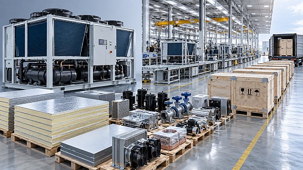
 Thermal FlowHardware Sourcing: How Procurement Teams Evaluate Suppliers, Lead Times, and CostHardware sourcing made smarter: learn how procurement teams assess suppliers, lead times, compliance, and total cost to secure reliable, high-value infrastructure.Dr. Julian VoltSep 23, 2026
 Rapid Site GearHow to Choose Cordless Power Tools for High-Volume Jobsite Work?Cordless power tools for high-volume jobsites: learn how to select reliable battery platforms, optimize runtime, improve safety, and reduce costly downtime.Marcus ShieldSep 22, 2026
 3D Steel ModulesHow to Vet a Prefabricated Construction Systems Supplier for Capacity and Delivery RiskVet a prefabricated construction systems supplier with proven capacity, quality controls, supply-chain resilience, and logistics planning to reduce delivery risk.Marcus ShieldSep 21, 2026
 High-Speed LiftsHow to Specify Gearless High-Speed Elevator Systems for Tall-Building TrafficGearless High-Speed Elevator Systems: learn how to optimize tall-building traffic, ride quality, energy efficiency, resilience, and lifecycle value with a smarter specification strategy.Dr. Victor GearSep 20, 2026